1 Overview
This document is intended as a practical reference for clients working on their own Vention automation projects with repeatability requirements. It covers how to evaluate whether a design can meet a given repeatability spec, how to avoid common assembly mistakes that introduce error, how to validate the controls setup, and how to measure repeatability in the field using accessible tools.
The document is organized as follows:
Defining Repeatability introduces the key concepts of repeatability, accuracy, uncertainty, and backlash, and explains how they relate to Vention deployments.
Design Phase covers how to calculate the theoretical repeatability of an actuator configuration, how to identify red flags in a design before committing to a spec, and how to come to a good estimate of a solution’s eventual repeatability.
Assembly Phase describes common assembly mistakes that contribute to repeatability error, and provides checklists for both mechanical assembly and controls setup.
Evaluating Repeatability describes a procedure inspired by ISO-230 to evaluate repeatability in the field, including the required tools and how to interpret the results.
Evaluating Accuracy discusses the limitations of measuring accuracy without specialized equipment and the approach taken on a case-by-case basis.
Repeatability Decision Flowchart provides a summary of the end-to-end process for ensuring a deployment with a repeatability requirement will succeed in production.
2 Defining Repeatability
In industry, repeatability is defined by two main standards:
ISO 230 (Europe)
ASME B5.54 and B5.57 (USA)
At a high level, repeatability is a measure of much variation can be expected between iterations of the same operation. Accuracy is the tendency, on average, to achieve the desired target
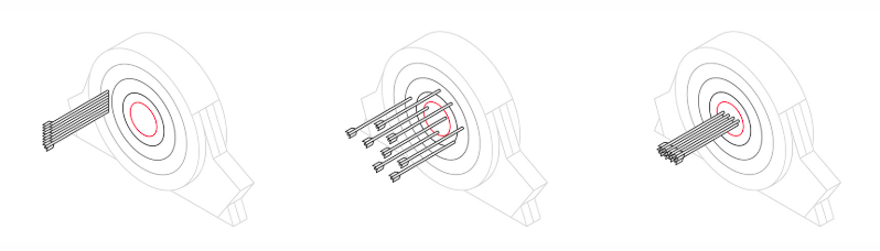 Figure 1: Repeatable but not accurate, accurate but not repeatable, repeatable and accurate. [1]
The main components of repeatability error in mechanical systems are uncertainty and backlash. Uncertainty represents the amount of random variation a random component can exhibit between iterations of the same operation due to manufacturing tolerances. Backlash is the predictable loss of travel of an actuator due to changing direction.
.png)
Figure 2: Illustration of mechanical backlash [2]. Note a set of gears are shown
In manufacturing, the potential of a machine to be accurate is most fundamentally limited by its repeatability. If its operation has high variance, there is nothing that can compensate. Fortunately, repeatability (both random and backlash) is relatively straightforward to quantify. Once a machine is repeatable, errors in accuracy can be compensated for with mechanical adjustments and software mitigation.
3 Design Phase
3.1 Some Characteristic Deployments
While not always explicitly given, every Vention automation solution has an implicit repeatability requirement. Vention's hardware is primarily aluminum and focused on a high level of modularity. As a result, the ecosystem is not optimized for high performance repeatability applications, however, performance on the order of +-0.5mm is definitely achievable. A common theme in Vention solutions that achieve relatively high repeatability is the selection of ball screws actuators.
3.2 Quoting Projects with Accuracy Requirements
Establishing the real life accuracy of a deployment under +-2mm is not straightforward, as it requires measuring absolute position error to a fraction of a millimeter. This can’t be done with conventional handheld tools. Accuracy characterization for Vention’s actuators is also , which leaves a large blind spot in terms of the accuracy limits of Vention built machines. As a result, Vention does currently quote any accuracy specs lower than +-2mm without a detailed plan to achieve it.
If you have an accuracy requirement, It’s important that you have a plan to evaluate it and that your ability to measure is within your performance requirements. An example of a made to order accuracy evaluation could be something like a calibrated go/no go sheet of paper. This sheet should outline the boundaries of acceptable operation. Mount the paper into a repeatable known location in the workspace and perform your process (laser welding, dispensing, etc.), ensuring that it falls between the boundaries.
3.3 Calculating Theoretical Repeatability of a Design
Designs with repeatability requirements should always start with a spec. Given this spec, there are some simple calculations to establish whether the design can perform. Table 1 outlines common Vention components and their contribution to repeatability error.
Component | Backlash | Total Repeatability | Mechanical Gain |
|---|---|---|---|
Enclosed Timing Belt | 0.275 mm | 0.325 mm | 208 mm/rotation |
Enclosed Ball Screw | 0.01 mm | 0.025 mm | 16 mm/rotation |
Rack and Pinion V2 | 0.275 mm | 0.325 mm | 141.37 mm/rotation |
Belt Rack | 0.275 mm | 0.325 mm | 141.37 mm/rotation |
5:1 Gearbox | 0.167 deg | 0.167 deg | N/A |
90 degree Gearbox | 0.167 deg | 0.167 deg | N/A |
Brake | 0.4747 deg | 0.4747 deg | N/A |
Servo Motor | 0 deg | 0.044 deg | N/A |
Self Aligning Mounts | N/A | 0 | N/A |
Table 1: Common Vention components and their contribution to repeatability error
A major component of backlash comes from unclamped keyed connections from a motor shaft to the actuator. Due to tolerances of the shaft key fit, this can contribute up to 0.474 degrees of backlash in a worst case tolerance stack. Advertised backlash values are derived from empirical testing and nominal measured values, which leaves the possibility to have slightly more backlash than anticipated in the unlikely case of a maximum clearance tolerance stack-up. To mitigate this, use enclosed ball screws or lead screws, which have clamping collars in their motor mounts. All gearboxes have these clamps as well, effectively eliminating backlash from shaft key clearances. During assembly, it is important to ensure that all shaft clamps are properly tightened to minimize potential backlash.
Note that while adding a 5:1 gearbox technically adds some mechanical repeatability error, it is best practice to add them in non-ball screw applications. This is due to the performance improvement on the controls side resulting from the addition of holding torque at low speeds.
In order to know how repeatable an application can be, it’s useful to make the following simplifications:
No repeatability error is attributed to thermal fluctuation
The assembly is assumed to be rigid, with all joints firmly tightened
Self aligning mounts do not contribute significantly to repeatability error when properly deployed
Controls are properly tuned, and controls repeatability is driven by encoder resolution
You can calculate a good starting point for how repeatable an individual actuator can be. Equations 1, 2, and 3 describe how to calculate a given actuator’s theoretical repeatability. The Uncertainty of a design is expressed as:
The backlash contribution (linear actuator backlash plus the linear equivalent of gearbox output is:
Theoretical repeatability is the sum of both contributions:
Where:
ja — linear actuator backlash (mm)
k — linear travel per motor revolution, gain, or linear displacement ratio (mm/rev)
θm — motor angular uncertainty (degrees)
θg — gearbox angular uncertainty (degrees)
n — gearbox ratio (= 5)
jg — gearbox angular backlash (= 0.192°)
jb — brake angular backlash (= 0.4747°)
Table 2 outlines common actuator configurations and their theoretical repeatability, including controls, linear and rotary components. These values represent the best case scenario for repeatability of a gantry. It is wise to attribute a margin of error on top of these numbers assessing the repeatability of a solution. A recommended baseline margin is 2x the theoretical repeatability.
Actuator Type | Uncertainty (mm) | Total Backlash (mm) | Theoretical Repeatability (mm) |
|---|---|---|---|
Enclosed Ball Screw | 0.017 | 0.010 | ±0.027 |
Enclosed Ball Screw + Brake | 0.017 | 0.031 | ±0.046 |
Enclosed Timing Belt + 5:1 Gearbox | 0.055 | 0.371 | ±0.426 |
Timing Belt + 5:1 Gearbox | 0.054 | 0.344 | ±0.398 |
Rack and Pinion V2 + 5:1 Gearbox | 0.053 | 0.340 | ±0.394 |
Enclosed Lead Screw | 0.025 | 0.125 | ±0.150 |
Enclosed Timing Belt | 0.075 | 0.275 | ±0.350 |
Rack and Pinion V2 | 0.067 | 0.275 | ±0.342 |
Belt Rack + 5:1 Gearbox | 0.053 | 0.333 | ±0.386 |
Belt Rack | 0.065 | 0.275 | ±0.340 |
Timing Belt | 0.068 | 0.275 | ±0.343 |
Common actuator configurations and their theoretical repeatability
Vention does not currently offer backlash compensation functionality at the firmware layer, so it is best practice to use the total repeatability value in design. If necessary, better performance can be achieved implementing backlash compensation at the application layer of a project.
3.4 Designing for Controls
Beyond the mechanical repeatability of a Vention system, under powered controls can also result in repeatability issues. Some guidelines for designing repeatable systems from a controls perspective are:
Select an actuator setup that has adequate holding force for your application. The amount of holding force should have a substantial safety factor over the calculated value. The holding force is a function of the actuator type, gearbox, and motor size. A good rule of thumb is >1000N, or at least Large motor with 5:1 gearbox on an enclosed timing belt.
For ease of deployment, single motor axes are preferred. Dual drive implementations are capable of delivering highly repeatable performance, but are more complex to assemble properly.
If dual drive is necessary, each motor requires its own home and end sensor. This requires a custom firmware on MachineMotion v2, and is natively supported on MachineMotion AI.
Note that this point is focused on actuators that are distinct from each other but operating in parallel as a single axis. If you have multiple motors connected to the same actuator for increased power/torque that is a separate configuration and this point can be disregarded.
If the system is dual drive, the positions of the home sensors should be easily adjustable. This usually entails an external mounting bracket for at least one sensor as using both the default mounting points on actuators does not allow for positional adjustment of the sensors.
Inductive home sensors can have variability in their depth of detection (along the axis of the sensor). To eliminate this potential variation, design the sensors so that they are triggered laterally (across the sensor) rather than axially (into the sensor)
If these guidelines are followed, repeatability concerns arising from controls can be well controlled.
3.5 Design Red Flag Checklist
Question | Solution / Mitigation |
Is my repeatability requirement unclear? | Negotiate and confirm what is needed with the client/application engineer. |
If I have an accuracy requirement, do I have a plan to evaluate it? | Create a plan to establish accuracy of the deployed solution |
Does my design include components that have no repeatability spec? | Replace components with known repeatable components |
What is the repeatability of my unknown components? | Test repeatability error with a prototype assembly |
Is the theoretical repeatability of my design unknown? | Lookup using Table 2 or calculate with Eq. 3 |
Is my margin for repeatability error below 2? | select more repeatable actuators such as ball screws or relax the repeatability spec |
Do I have an axis longer than 1m and do I expect to see temperature variation >10C? | Validate with Vention engineering to confirm repeatability impact |
Is my design sufficiently rigid? | Review the design with an application engineer and add bracing where necessary |
Does my design have dual actuator axes and does my design allow for adjustment of home sensors? | Plan for adjustable sensor placement on the secondary actuator |
Does my design have sufficient holding force? | Calculate the safety factor on holding force. It should be at least 2 if you are in a repeatability or accuracy critical application. If it is too low consider adding a gearbox or changing actuator type |
Are my home sensors oriented to be triggered across their face? | Design the mounting so sensors are triggered by crossing the detection range, rather than entering depth-wise |
In summary, repeatability requirements are driven by a solution’s manufacturing process. Vention’s actuators and gearboxes have known repeatability specs, which can be used to calculate a best case scenario for repeatability of a solution. If using parts that move that have unknown repeatability, it is important to test how they will contribute to error and factor that into repeatability claims in the design phase. In practice, other sources of repeatability error, such as temperature, wear and less than perfect assembly can all contribute to repeatability error in a way that is difficult to quantify, so a margin on this calculated number should be applied. Before signing off on a project,
the checklist in Table 3.5 should be reviewed to ensure that repeatability claims can be delivered.
4 Assembly Phase
While primarily affecting accuracy, the assembly of a machine can also contribute to repeatability error in a variety of ways. Besides straightforward things like properly tightening joints, etc, there are key points to be aware of that can affect the accuracy and repeatability of a machine.
One common mistake is the improper assembly of self aligning mounts. On dual gantry axes, self aligning mounts can be helpful to mitigate assemblies which are slightly out of square and out of parallel. They do this by fixing one actuator in place while allowing lateral translation and rotation of the other. As a result, all leader mounts (fixed) must be mounted to one actuator and all follower mounts on the other. It is also necessary for follower mounts to be oriented so their translation is perpendicular to the motion of the actuator. If the mounts are improperly assembled, this allows both actuators to translate freely, adding multiple millimeters of repeatability error. Every assembly using self aligning mounts should verify that they are mounted correctly.
|
|
The leader mount is equipped with a spherical bushing. When multiple are connected in line it creates a single RDOF (rotational degree of freedom) to allow for angular misalignment. | The follower mount allows for the same RDOF as the leader to compliment it while also allowing for a single axis of translational degree of freedom. |
.png)
.png)
For additional information on the proper usage of self-aligning mounts, read through the technical documentation on the product.
In cases of parallel actuators that are not using the self-aligning mounts special care must be taken to properly align the bearing systems for both longevity and performance. Refer to the Vention Linear Axis Alignment Procedure
Another common mistake is with dual gantry assemblies, where one actuator is mounted skewed with respect to the other. Not only does this reduce the total travel of the axis, but if combined with dual sensors, this can cause internal torques in the system at rest, as each motor will have to slightly deform the structure to hold its position. This can be very easy to overlook, and make it appear that there is a controls issue. Some straightforward ways to evaluate this part of the assembly is to check the mounting with a T-square, or by estopping the machine, pulling the axis back and verifying that both sensors are naturally triggering at the same location in its travel in a zero stress scenario.
Given the actuators are properly mounted, it is also worthwhile to check whether the motion of the axes is parallel with the desired work area. This can be done by mounting an indicator to the gantry and moving along a known linear reference (e.g. the edge of a machined plate). Any runout/change in depth of the indicator should be adjusted in assembly to within the necessary specifications for your application.
Overall, before moving forward to characterize the controls and repeatability of a machine, it is worth double checking overall perpendicularity of axes as well, such as with a T-square, measuring tape (for measuring diagonals), or with the "3-4-5" method. These are coarse methods of measurement, but can catch large perpendicularity problems before moving onto controls.
Another potentially blocking issue during assembly is larger backlash than expected. A major source of extra backlash error comes from keyed connections between the actuator and motor/gearbox/brake. While motor keys are made to tolerance and pass outgoing quality procedures, if unexpected backlash is observed, they are one possible culprit. In spec motor shaft keys are made to 5mm +0/-0.03. These keys can wear over time and are worth measuring with calipers for verification. Additionally, when using a rack and pinion actuator it is possible to have assembly tolerance stack up that leads to an improper pinion engagement and therefore out of spec backlash. Pay particular attention to pinion engagement and backlash on rack and pinion assemblies.
4.1 Mechanical Assembly Checklist
It's useful to run through this checklist to make sure major assembly problems are avoided:
Question | Solution / Mitigation |
|---|---|
Are my self aligning mounts assembled in the correct orientation, with leaders on one actuator and followers on the other? | Re-mount them appropriately |
Are all my motor shaft keys within 5mm +0/-0.03? | Replace any worn keys with in-spec units. |
Is the internal shaft clamp in my gearbox tightened? | Tighten the gearbox clamp with a 4MM T-Handle |
Is there any physical slop/play in any of my assembled joints? | Tighten fasteners, increase rigidity with bracing, inspect for design flaws that introduce undesired backlash |
When motors are powered on and holding, is there any noticeable backlash/play when pushing my actuators back and forth? | tighten mounting of motors, check if shaft keys are within tolerance, check if gearbox clamp is tightened |
Is my dual gantry reasonably square and parallel? | Loosen assembly, manually adjust for squareness, re-tighten |
Are my other gantries plumb and square with respect to each other? | Fine tune assembly |
Is there anything else in my assembly that has the ability to move under minimal force? | Adjust the design by removing the component or improve fixation |
With motors powered, but in estop, do both my home sensors trigger roughly in the same place? | Large error: Move one actuator forward with respect to the other until both sensors naturally trigger roughly at the same place. Small error: adjust with external sensor mount |
Are my actuators mounted in line with the axes of my workspace? | Adjust orientation of the work area |
Moving from beginning to end of travel, do I observe a lot of movement in self aligning mounts? | Consider adjusting parallelism of gantry to minimize self aligning mount travel if the follow mount is translating more than 2mm. |
4.2 Controls Checklist
The controls repeatability of a machine is driven by 3 main factors:
The system has adequate holding torque to account for forces during operation and minor imperfections in assembly
If at rest, home sensors are placed such that synced axes require minimal torque to hold position
In situations with unusually high speeds, loads, accelerations, whether the system has a tuned control loop
To satisfy point 1, systems with less than 1000N of holding force per mechanical actuator are not recommended. If performing processes that involve external forces on the end of arm tool (e.g. engraving, routing), consider designing even more reserve force. This can be achieved with ball screws or lead-screws. Satisfying the second item involves adjusting the location of the home sensors as a result of the measured torque difference between motors in a synched axis. Both MMAI and MMv2 have end-points for reading the current output torque of each motor, and utilities can be provided on request to easily determine the total home sensor offset that is measured on an assembled machine. Figure 3 shows an example of two drives fighting each other due to home sensor misalignment, visible as opposing torque readings at rest.
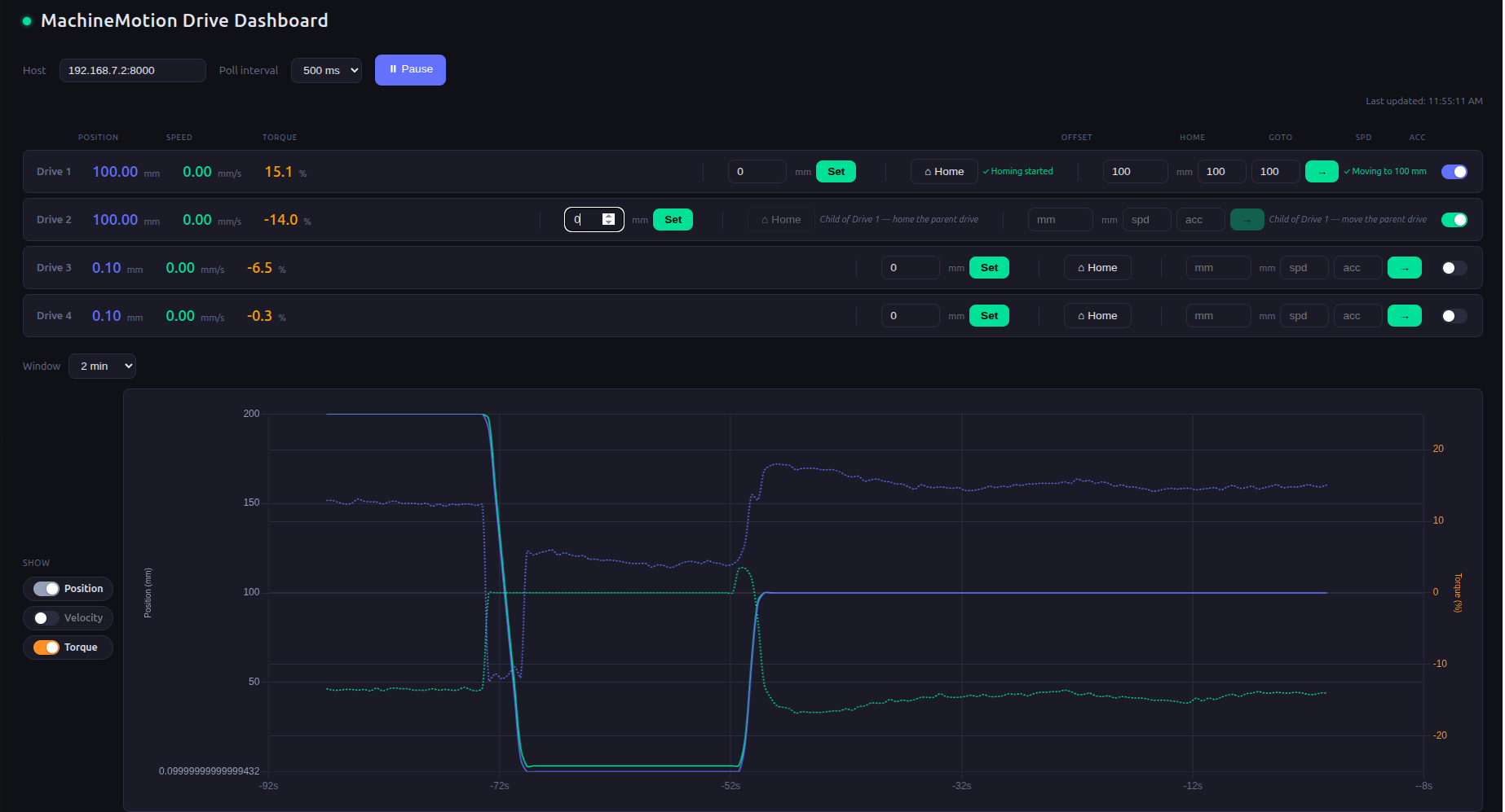
Two drives fighting each other due to home sensor misalignment. Drive 1 reads +15.1% torque while Drive 2 reads −14.0% at rest.
Satisfying item 3 will usually involve looking at the step response of axes and determining a custom pid profile that better suits the application. Note that this is generally the last adjustment to be made after ensuring design and assembly best practices are followed. Systems with under powered motors or misaligned actuators cannot be substantially improved with a custom tuning profile.
Question | Solution / Mitigation |
|---|---|
Does my system have >1000N of holding force? | Add gearbox, change motor size, change actuator |
After homing, do my motors pull against each other by more than 5% total? | Adjust location of actuator and/or home sensor |
Do I need to adjust my home sensor by more than 5mm? | Consider adjusting the assembly of the actuator itself |
Does my servo position settle to within my repeatability tolerance? | Consider adding a gearbox (more control resolution, more torque), increasing Integral gain of controller. In both situations first eliminate home sensor misalignment |
For the most part issues seen at the controls level are more symptoms of a design or assembly issue. Before trying to run a custom tuning profile, design and assembly solutions should be pursued. If design and assembly already pass their own respective checklists, tuning can mitigate remaining controls problems.
5 Evaluating Repeatability
5.1 Required Tools
Industry standard ways for measuring repeatability and accuracy involve expensive optical systems that are costly and require expertize to operate. they have the advantage of being able to simultaneously measuring accuracy and repeatability at very high resolution. It is not generally feasible to achieve high degrees of accuracy/repeatability performance without either purchasing these tools or hiring a third party to perform the evaluation for you.
A reasonable compromise for evaluating repeatability is a digital dial indicator with usb capture. while manual recording of data is possible, The ISO-230 procedure involves taking a minimum of 50 readings, making this process tedious. A recommended set of tools for measuring repeatability is:
digital calipers for measuring motor shaft key (e.g. Mitutoyo 500-151-30)
digital dial indicator with usb input capture (e.g. Mitutoyo 543-790-12)
usb cable compatible with the indicator (e.g. Mitutoyo 06AFM380F)
high quality indicator stand magnetic base (e.g. Mitutoyo 7033B)
steel mounting bracket compatible with vention extrusion (e.g. Vention HW-TL-013-0001)
heavy, flat, square steel square block to use as a reference (e.g. 123 block or a precision 90 degree angle plate)
5.2 Process
The following is simple a description of the process defined in ISO-230. Because of a lack of interferometer, repeatability is calculated independent of accuracy. This is done on a per-axis basis. For an individual axis, select 5 random locations along its travel. For each point:
home the actuator, then travel to the point
orient the indicator so it is perpendicular to the axis travel
place the block roughly midway into the indicator’s detection range and zero it.
then, five times:
home the axis, move to the location, take a reading off the indicator
move forward 3mm, move backward 3mm, take a reading off the indicator
calculate the difference in reading between positive and negative, this is your backlash for that sample.
for each direction, calculate the sample standard deviation of indicator readings. that is your uncertainty in that direction
The backlash (also called reversal error) at each point i is the difference of the average readings at i in each direction:
The uncertainty at each point i in each direction is the sample standard deviation of the indicator readings:
After going through all five points, take the worst recorded backlash and the worst recorded uncertainty in each direction.
The repeatability is:
σ+ — sample standard deviation of indicator readings in the positive direction
σ− — sample standard deviation of indicator readings in the negative direction
j – worst recorded backlash (mm)
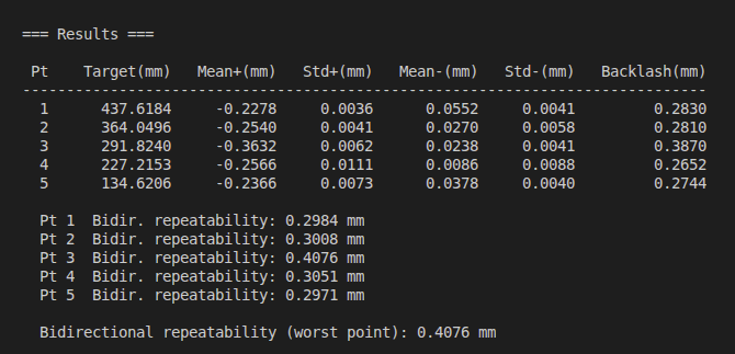
Example results of an automated repeatability procedure
6 Evaluating Accuracy
Accuracy cannot be achieved without repeatability. As a result, any effort to evaluate accuracy must be done after establishing repeatability as in the previous section. Without expensive tools, it is difficult to measure accuracy. This is because accuracy requires a measure of absolute error with respect to a known reference. An industry standard measurement for accuracy requires 5 known absolute positions in the workspace for each axis that can be physically measured against the end of arm tool. The locations used in the previous section were arbitrarily selected, and absolute error was eliminated by taring the indicator at the block.
As a result, no standard process can be proposed to evaluate the accuracy of Vention solutions and solutions need to be developed on a project to project basis. Because of the need for absolute measurements, and the low resolution of commonly available tools, accuracy claims can be more than an order of magnitude worse than repeatability. Note that a good rule of thumb is that the resolution of measurement of any spec (repeatability or accuracy) should be 10x the desired performance. Meaning, if you have an accuracy spec of +-1mm, it is best practice to be able to measure at +-0.1mm.
If the sale of a project requires a claim on accuracy, it is critical that a plan to evaluate accuracy is developed and agreed upon by the client.
One high level approach to evaluate accuracy is as follows: first, identify some known absolute references within the design. This could be on a fixed machined part such as a plate. take one absolute locations (such as the edge of a plate) and define it as an origin. Tare a dial indicator at that origin, then move the known distance to another known point (such as a block fixed at the end of the plate). As with repeatability, take 5 samples per direction per point. Calculate the average error in each direction for each known point. Using the previously obtained uncertainty values, the accuracy can be estimated by:
7 Repeatability Decision Flowchart
7.1 Before the Factory Acceptance Test
With the context of previous sections, there is a procedural way to make sure a deployment with a repeatability requirement is successful. If included in a turnkey project, this process must be performed prior to the factory acceptance test. Any project with a repeatability requirement should have a written document detailing the measured repeatability of the machine.
The first step is always to confirm the requirement before starting design. As a rule of thumb, a design should be developed with a theoretical repeatability of at least twice the spec needed by the client. Before finalizing the design, it is worth checking whether there are any parts that lack repeatability numbers, whether controls will perform and whether the assembly can be adjusted to account for alignment issues. The checklist in Section 3.5 is a good starting point to build confidence in a prospective project.
In the commissioning phase, it is easy to miss issues of alignment, parallelism and backlash in the system. The checklist in Table 4.1 can be a useful tool to avoid falling into some common issues during assembly.
The controls evaluation depends on proper design and assembly. It is common to need to adjust the location of home sensors, but less common to need a custom tuning profile. The checklist in Table 4.2 can help to determine the best course of action. There are automated scripts for determining the home sensor offset, which can be provided on request.
Once design, assembly, and controls are validated, the repeatability evaluation outlined in Section 5.2 should be performed and documented. If using the recommended indicator and usb cable, an automated version of this procedure can be provided on request.
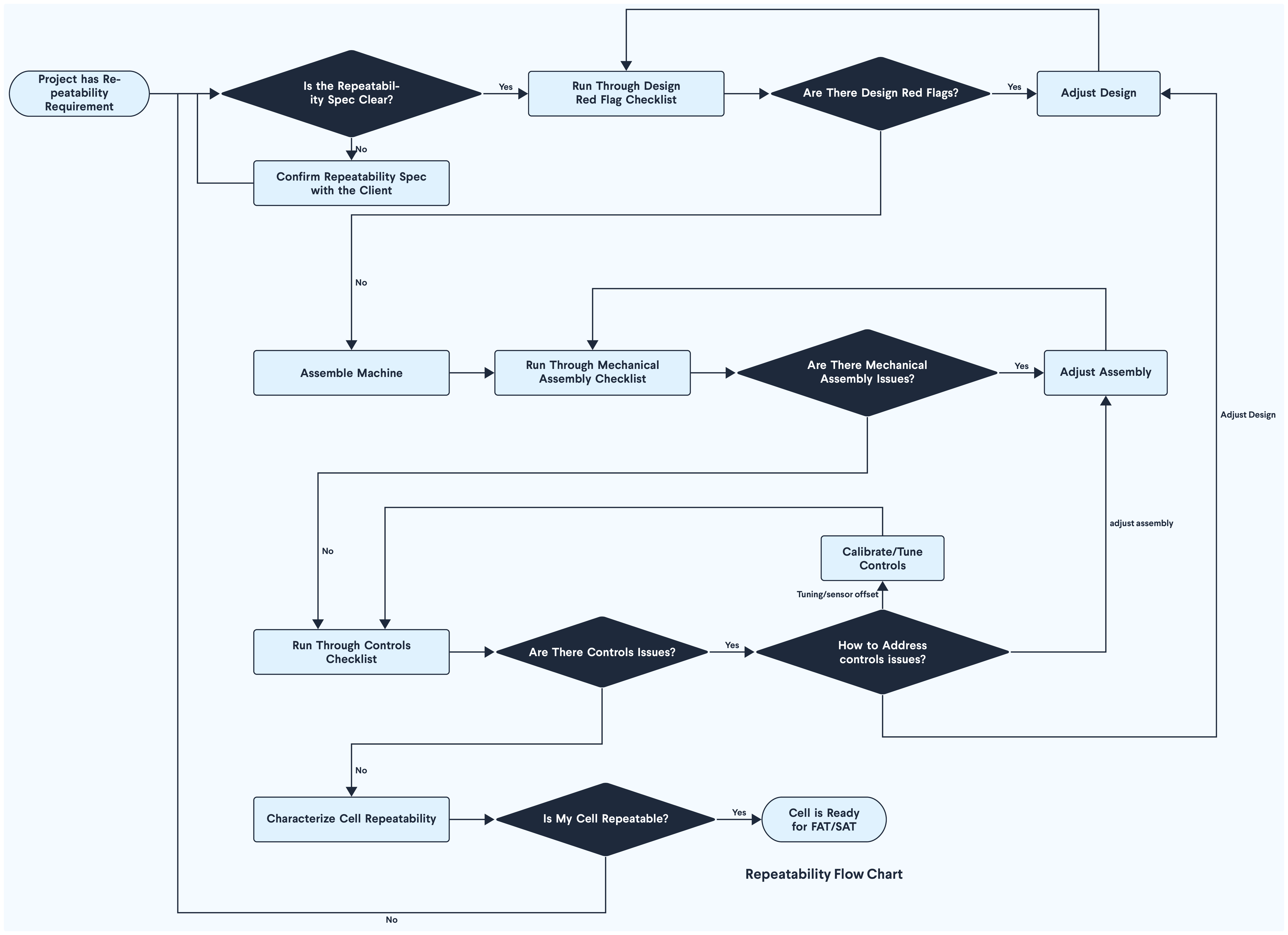
Repeatability commissioning workflow
8 Conclusion
Repeatability is a fundamental requirement of any automated manufacturing process, and achieving it reliably requires attention at every phase of a project. While Vention hardware is capable of delivering repeatability on the order of ±0.5 mm, this performance is only achievable when the design, assembly, and controls are all properly executed.
At the design phase, the theoretical repeatability of a solution should be calculated using the component specs outlined in this document and compared against the client requirement with a safety margin of at least 2×. Components with unknown repeatability specs should be identified and either replaced or empirically tested. Accuracy requirements demand a separately agreed evaluation plan, as Vention has not internally validated its actuators for absolute accuracy.
During assembly, common failure modes include mixed self-aligning mount orientations, skewed dual-gantry actuators, and worn motor shaft keys. Each of these can introduce repeatability error that is difficult to compensate for in controls or software. The mechanical assembly checklist in section 4.1 provides a practical starting point before proceeding to controls evaluation. Controls issues are most often symptoms of upstream design or assembly problems. The most common controls–level source of repeatability error is an underpowered system — one that lacks sufficient holding torque to maintain position consistently. Home sensor misalignment between synced drives is the next most common issue, and should be corrected by adjusting sensor positions rather than by tuning the control loop. Only once design and assembly pass their respective checklists should custom PID tuning be considered.
Finally, repeatability must be measured, not assumed. The ISO-230 based procedure described in Section 5.2 provides a method for quantifying both uncertainty and backlash on a per-axis basis using accessible tools. The results should be documented and reviewed against the client requirement before any factory acceptance test.
References
[1] ABB Measurement Products, Are accuracy, precision and repeatability the same thing?,
https://new.abb.com/products/measurement-products/measurement-products-blog/are-accuracy-precision-and-repeatability-the-same-thing
[2] en:User:GearHeads, User:Slashme, Backlash (engineering) diagram, Redrawn from w:File:Backlash.jpg, CC BY-SA 3.0, https://commons.wikimedia.org/w/index.php?curid=10269408