This how-to guide covers how to program your collaborative robot using MachineLogic.
MachineLogic is Vention’s cloud-based authoring tool for programming industrial automation. All programs can be simulated in the cloud environment or deployed and executed on the MachineMotion controller. For an introduction to MachineLogic Code-Free programming, see How to configure, program and simulate with MachineLogic. For learning how to program your automation in Python, read the MachineLogic Python Programming Guide.
This guide provides information on the latest release for Robot Programming and Scene Assets in MachineLogic. For details on previous releases, refer to the Documentation for Previous Releases section at the bottom of this page.
1 - Robot Configuration
In order to create robot programs in MachineLogic, you must add a robot and a MachineMotion controller to your design.
.png)
Figure 1: Robot in MachineBuilder
Click the Configuration tab on the right to begin configuring the automated equipment.
Select the robot you would like to configure, and set the parameters:
Name: Friendly name used for the robot in MachineLogic applications.
Robot: The corresponding robot model in the design. Please note that MachineLogic only supports a single robot at the moment.
Default tool center point: One of the configured TCP entries that will be used unless the MachineLogic application explicitly requests another.
For each TCP configuration, you can define its parameters:
Tool center point: Tool center point offset values. By default, they are set according to the dimensions of the end of arm tool parts connected to the robot flange. You can edit them manually, or click "Use end-of-arm tool values” to reset them to the default values.
Tip: TCP orientation dictates the pose of the robot when reaching a cartesian target. By default, the orientation of the Z-axis points directly outward from the robot flange
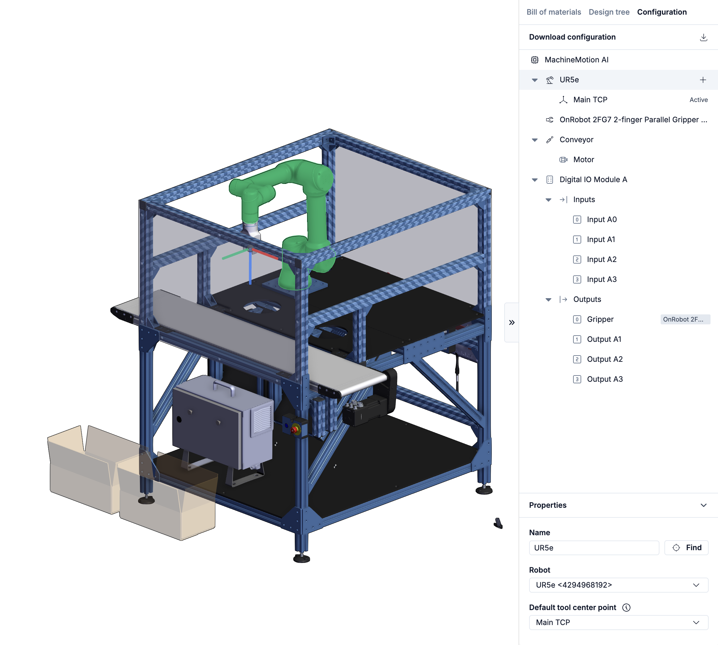
Figure 2: Robot configuration
2 - Scene Assets Pane
The sections below outline all robot functionality available for you to program your next robot application.
To learn more about the basics of MachineLogic’s code-free programming before getting started, click here.
The “Scene assets” side-pane in MachineLogic allows you to create assets useful for programming robot motion. These assets consists of frames and targets that can be reused across applications in the same design, or scoped to a single application.
The scene assets are nested in a tree-view structure where children asset’s positions and orientations are always defined relative to their parents.
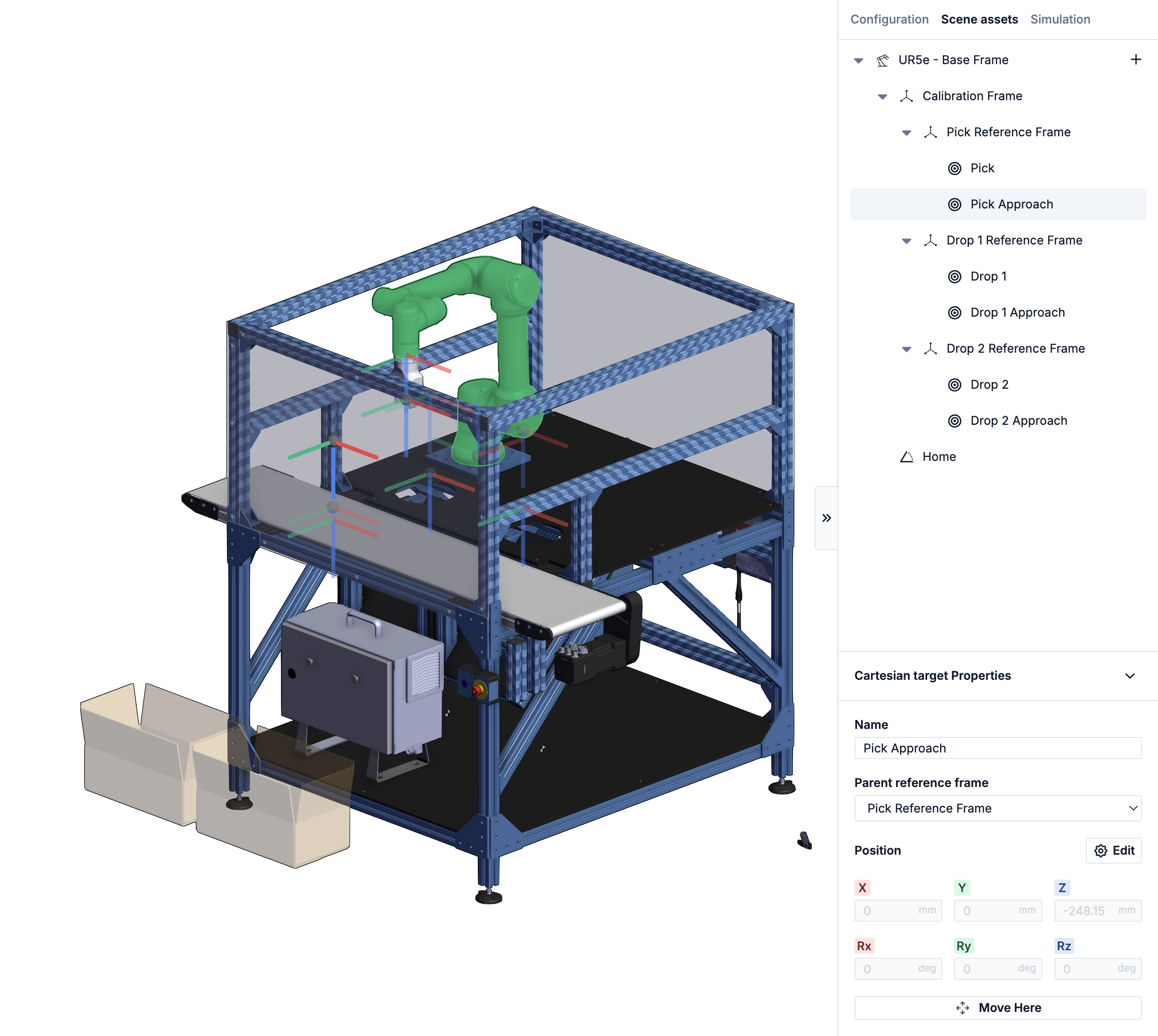
Figure 3: Robot in MachineLogic with Scene Assets showing
2.1 - Scene assets type
The available assets are:
Calibration Frame : A reference frame defined relative to the robot’s base frame. This frame can be used to define a coordinate system from which a set of reference frames or cartesian targets are defined. The nominal pose of the calibration frame is defined in the digital twin and can be calibrated in the physical world. Once the physical values are input in the controller, the difference between the nominal values of the digital twin and the calibrated values of the physical twin are displayed in the scene asset properties on the MachineMotion controller (see figure 4 below).
Reference Frame : A reference frame must be defined relative to a calibration frame. This frame can be used to define a coordinate system within which a set of cartesian targets are placed.
Cartesian Target : A target that the robot will attempt to reach when using the “Move robot” instruction. This target is defined in relation to its parent’s position and orientation.
Joint Target : A target that the robot will attempt to reach when using the “Move robot” instruction. This target is defined using the 6 joint rotations.
Tip: When inserting cartesian targets, be mindful of their orientation. The direction of the Z-axis of the target should match that of the defined TCP.
.png)
Figure 4: Calibration frame displaying the difference between digital and physical twin positions
2.2 - Inserting new scene assets
Inserting new scene assets can be done either by selecting the “Plus” icon at the left of the robot node, or through the context menu that opens when right-clicking an existing scene asset.
2.2.1 - Inserting a scene asset using the “Plus” Icon
Clicking the “Plus” Icon opens up the scene assets menu, with options to create any of the available scene asset kinds. Note that a calibration frame is required in order to insert reference frames or cartesian targets.
If an application is currently opened, the assets menu will contain application-level asset kinds, shown in blue. Application-level assets can only be used within the current application, while design-level assets are accessible to all applications contained within the design. Calibration frames are strictly design-level assets.
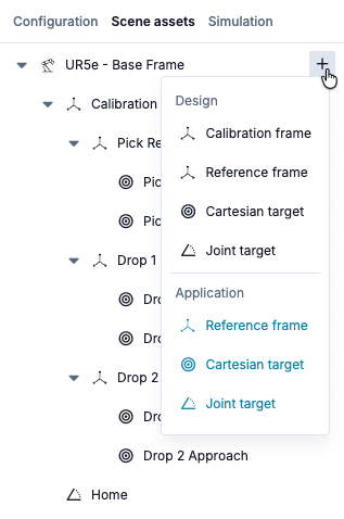
Figure 5: Inserting scene assets
2.2.2 - Inserting a scene asset using the context menu
It is also possible to insert new scene assets by right-clicking an existing calibration frame or reference frame. The context menu that appears will display the possible child assets that can be inserted under the selected frame, along the usual asset operations.
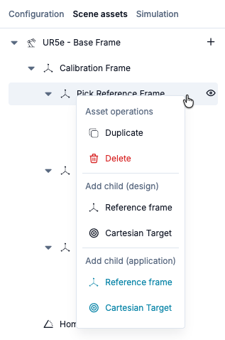
Figure 6: Inserting Scene Assets with context menu
2.3 - The properties pane
The properties pane is displayed when an asset has been selected in the tree. It displays the editable values of the selected asset and changes the view mode of the corresponding scene gizmo.
Calibration Frame Properties :
Name: User-defined friendly name of the asset.
Position: the position and orientation as defined with respect to the asset’s parent.
Reference Frame Properties :
Name: User-defined friendly name of the asset.
Parent reference frame: the parent of the selected asset, changing the parent will update the tree-view accordingly.
Position: the position and orientation as defined with respect to the asset’s parent.
Cartesian Target Properties :
Name: User-defined friendly name of the asset.
Parent reference frame: the parent of the selected asset, changing the parent will update the tree-view accordingly.
Position: the position and orientation as defined with respect to the asset’s parent.
Joint Target Properties :
Name: User-defined friendly name of the asset.
Joint Angles: the individual joint values of each of the robot’s joints.
Note: Rotation Values labeled Rx, Ry and RZ are described using Euler Angles
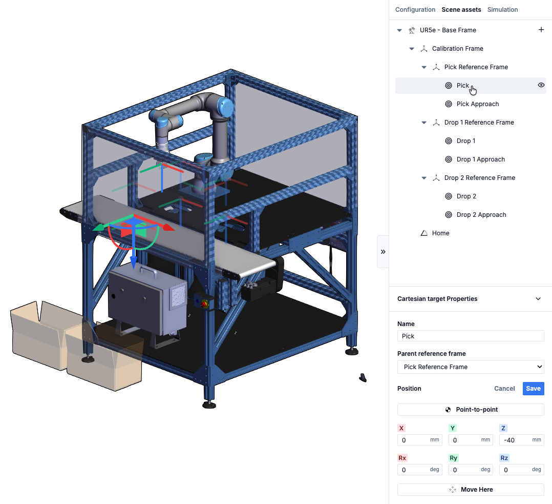
Figure 7: Properties of a Cartesian Target
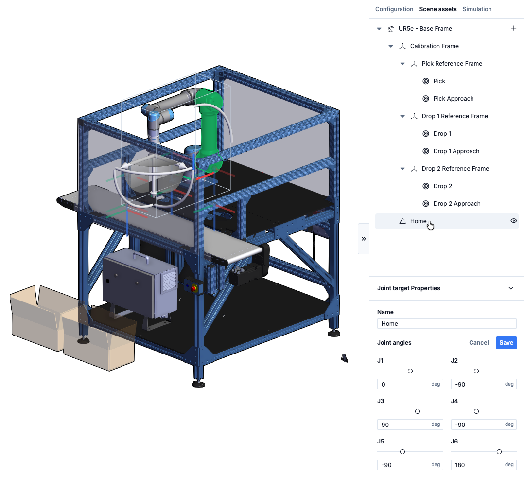
Figure 8: Properties of a Cartesian Target
2.4 - Editing the asset’s pose (edit mode)
To edit the position of an asset, click the edit button from the asset’s properties.
When in edit mode, there are three ways to change the asset’s position:
Drag the triad in the scene : When in edit mode, the asset’s gizmo will change to a triad. The triad allows for linear and planar translation and elemental rotations. The position fields will update to show the asset’s new positions.
Point-to-Point : The point-to-point feature automatically updates the position of the asset in accordance with the position of the cursor when clicking in the scene.
Input numerical values : It is possible to change the asset’s position by inputting numerical values directly in the position fields.
Tip: When using point-to-point, the Z-axis of the inserted scene asset will point downwards to match with default TCP values.
2.5 - Asset operations (context menu)
Asset operations are accessed from the context menu:
Duplicate : When duplicating a parent, the child assets will be duplicated as well.
Delete : When deleting a parent, the child assets will be deleted as well.
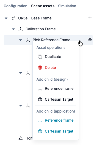
Figure 9: Context menu showing Asset Operations
2.6 - Using expressions and variables in application-level assets
Scene assets can either have design and application scopes. Design-level assets are accessible to any application in the design whereas application-level assets can only be used in the application in which they were created.
Application-level assets may use expressions and variables from the application in their fields. This can be helpful for certain applications where the same motion is repeated in a number of different positions. Follow the steps below when using an expression or a variable to define either a Reference frame or a Cartesian Target:
Step 1 - Define the variables that will be used to define the scene asset’s position from the left hand pane in MachineLogic.
Step 2 - Insert an application-level scene asset (Reference Frame or Cartesian Target) from the scene assets pane.
Step 3 - From the newly created asset’s properties, toggle the f(x) button.
Step 4 - Input the variable or function name in the corresponding position input field.
Once the application-level scene asset has been defined, use a loop instruction to loop a sequence containing a “Move robot” instruction along with a “Set variable” instruction to update the variable’s value with each loop iteration.
Tip: to repeat the same robot motions at different positions in the scene, use variables for a reference frame that contains all the cartesian targets. See this design for an application example.
2.7 - Uploading, editing and creating scene assets on the MachineMotion controller
Scene assets are intended to facilitate the deployment of programs from the digital twin to the physical twin. As such, the recommended workflow is to change the program from the digital twin before redeploying it to your target MachineMotion controller. However, it is still possible to edit and create new scene assets from the MachineMotion controller for times when modifications must be done directly on site or when no internet connection is available.
Scene assets are bundled with the application when downloaded from Vention.io and uploaded to your controller. To learn more about deployment, click here.
To access scene assets on the MachineMotion controller from a new application, select the “Scene Asset” section in MachineLogic’s left pane:
.png)
Figure 10a: Accessing scene assets on controller from MachineLogic
You can also access design-level scene assets (but not application-level scene assets) from the global navigation menu:
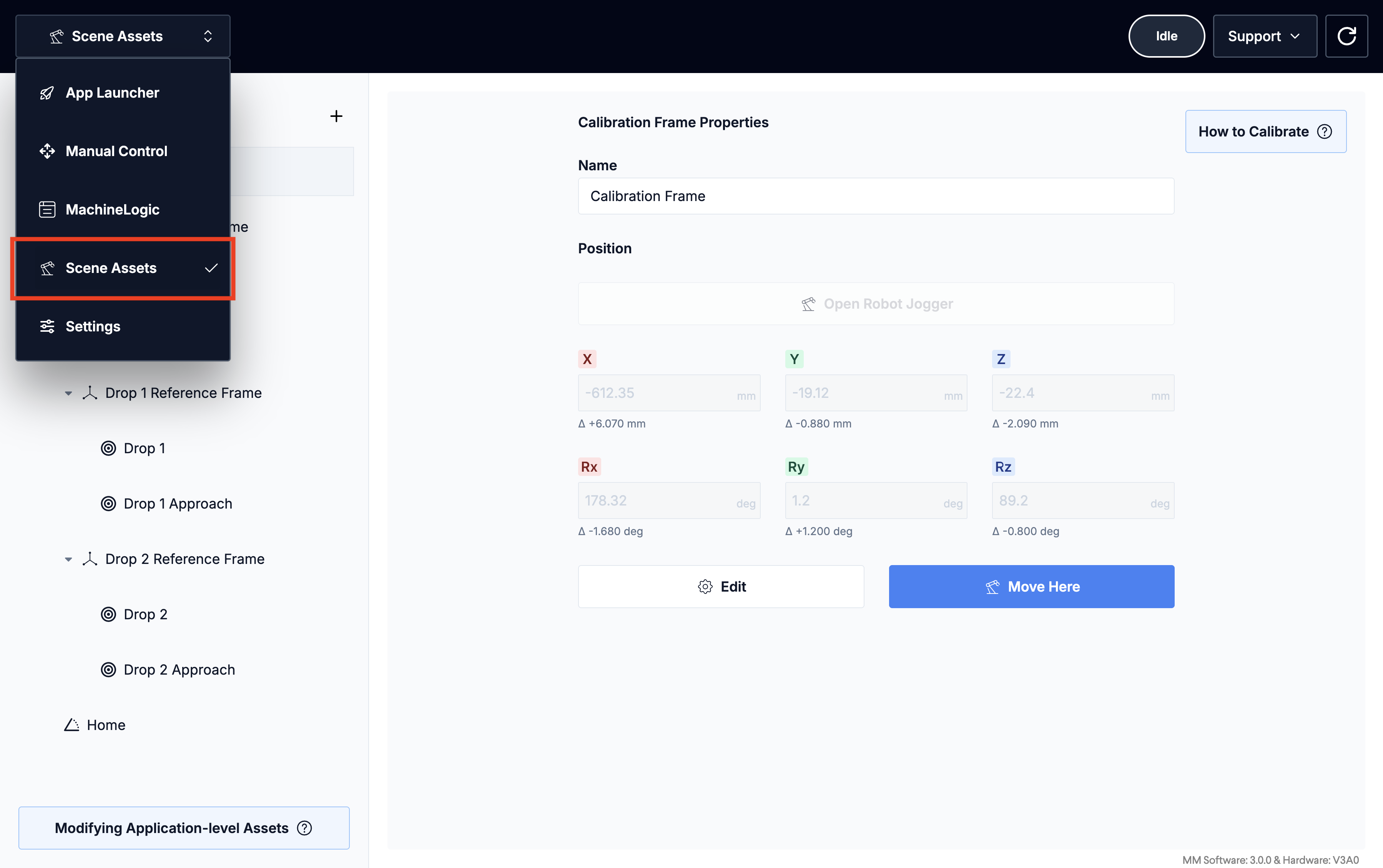
Figure 10b: Accessing scene assets on controller
To edit or create scene assets on the controller, either enter numerical values in the input fields or use the jogger to teach positions:
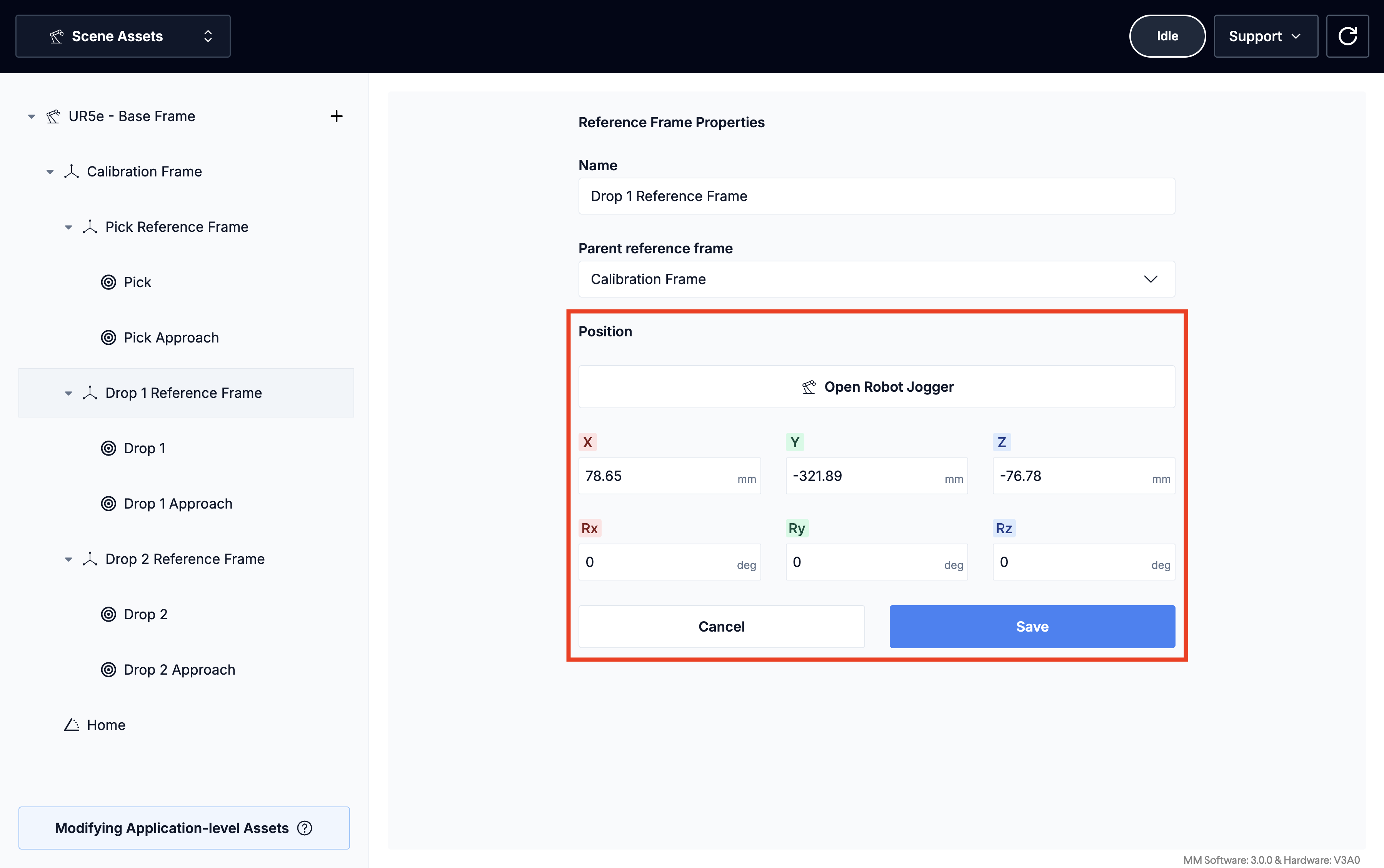
Figure 11: Editing scene asset properties from the MachineMotion controller
2.8 - Using the calibration app
As discussed in section 2.1, calibration frames contain two sets of values: nominal values as defined in in the cloud, and calibrated values used when the application has been deployed, to account for positional differences between the digital and physical twin.
To use the calibration app, download the application and upload it to your MachineMotion controller. Once uploaded, play the calibration app and follow the guide to compute a calibrated value for your calibration frames. Once calibrated, the calibration frame will show the differences between the default values from the digital twin and the new values as computed by the calibration app.
3 - The “Move Robot” Command
To move the robot, use the scene assets created above in a “Move robot” command.
3.1 - Inserting a “Move Robot” command
The “Move robot” command can be inserted from the “Add command” menu as shown below:
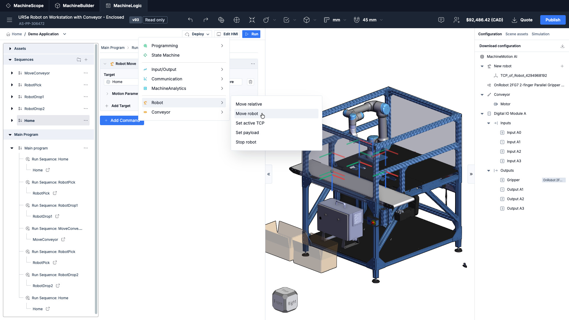
Figure 12: Add “Move robot” Instruction
3.2 - Adding targets and configuring the “Move robot” command
Once the “Move robot” command has been added to a sequence, click the “Add Target” button to access the motion parameters, including the target assets and the move type. Multiple targets can be appended to the “Move robot” command.
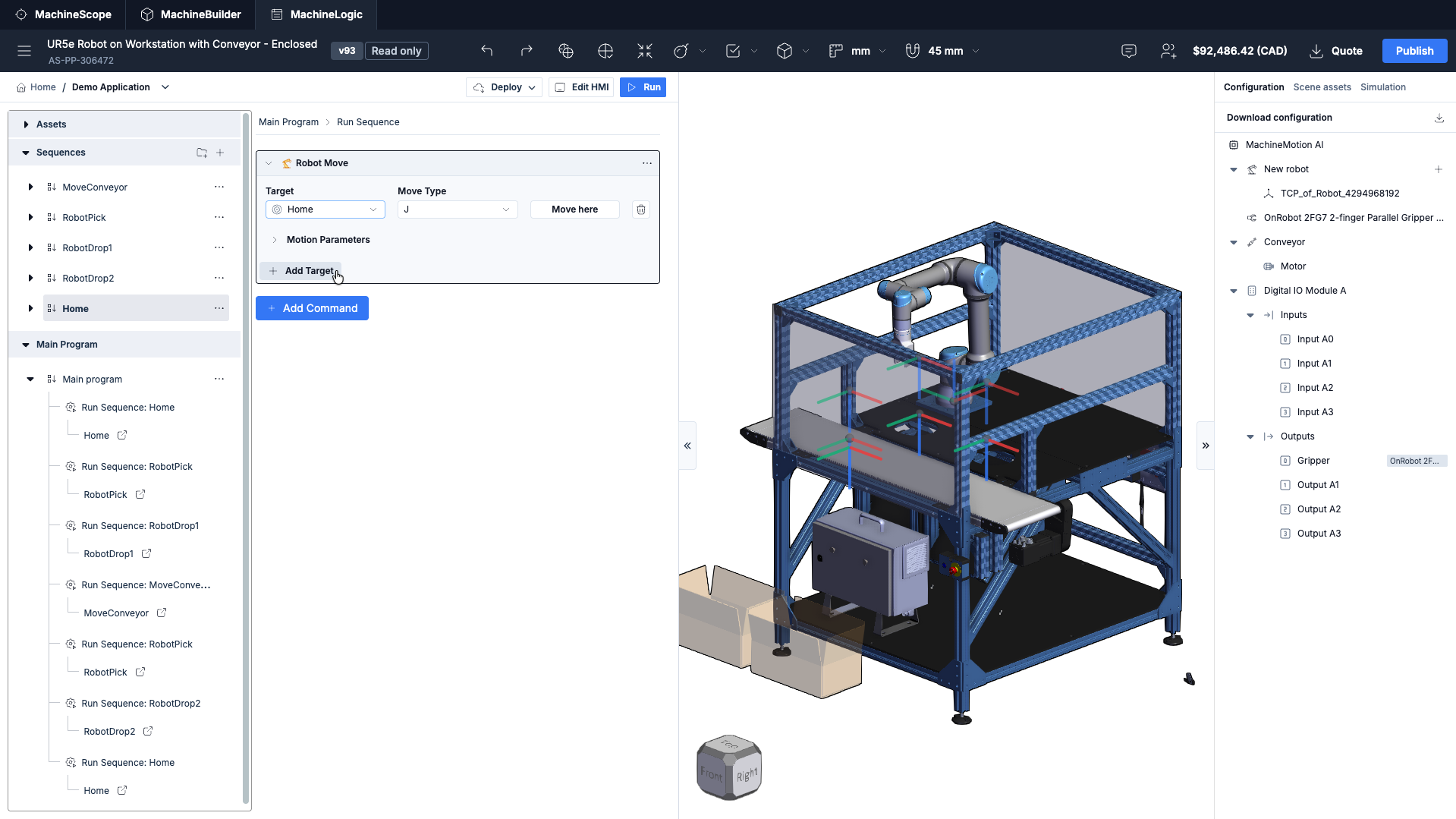
Figure 13: Adding targets to the "Move robot" Instruction
Once a target is selected, the following parameters will appear:
Target : This drop-down field displays all available targets as defined in the scene assets pane.
Move Type: Specifies the type of motion to be used to reach the target, either “Move J” or “Move L”. “Move L” will constrain the motion to follow a linear path.
Tip: It may sometimes be impossible to prepare a motion plan for a “Move L” motion, due to the linear trajectory constraint. If you experience a “Move L” failing to plan the motion, try changing the move type to “Move J”.
Move Here: This button can be used to visualize the resulting robot pose when reaching the selected target.
Under “Motion Parameters”, you can find the following options:
Tcp Speed: For “Move L” motions, the desired maximum TCP speed defined in mm/s.
Tcp Acceleration: For “Move L” motions, the desired maximum TCP acceleration defined in mm/s2
Joint Speed: For “Move J” motions, the desired maximum joint rotation speed defined in deg/s.
Joint Acceleration: For “Move J” motions, the desired maximum joint rotation acceleration defined in deg/s2
Blend Radius: The Blend Radius parameter can be used to program a smooth motion of the robot arm. The parameter defines a tolerance value for the path to deviate from the current target in order to conserve speed towards the next target in the list. This parameter is disabled for the last target in the “Move robot” command.
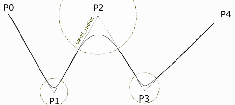
Figure 14: Blend Radius
4 - Robot State Reporting & Troubleshooting
Over the course of the robot’s physical programming and operation, you may encounter certain robot states and errors. The sections below outline those states, as well as how to troubleshoot them in the event of an error occurring. The sections will also cover best practices for programming your robot with MachineLogic.
4.1 - Robot states
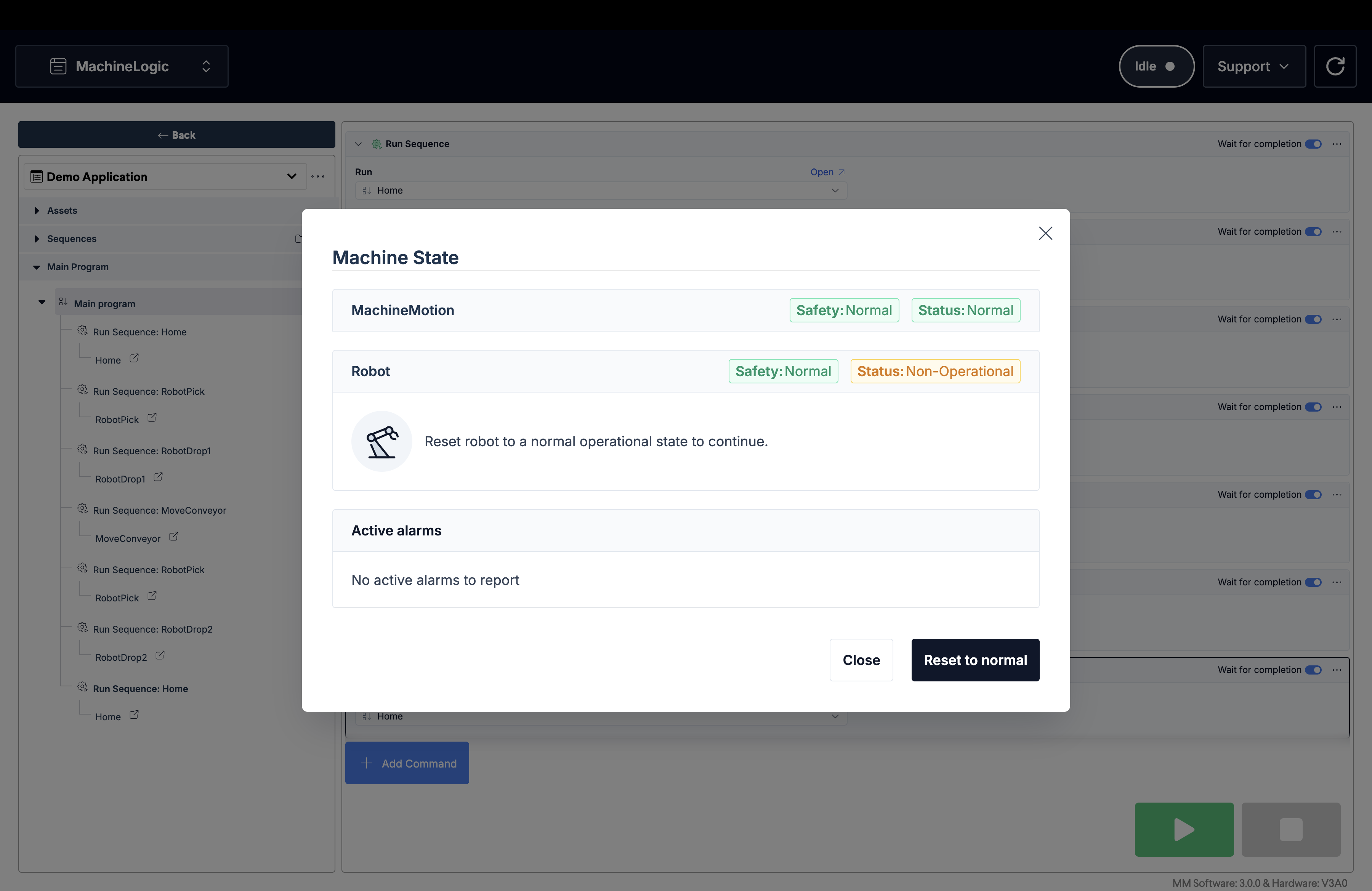
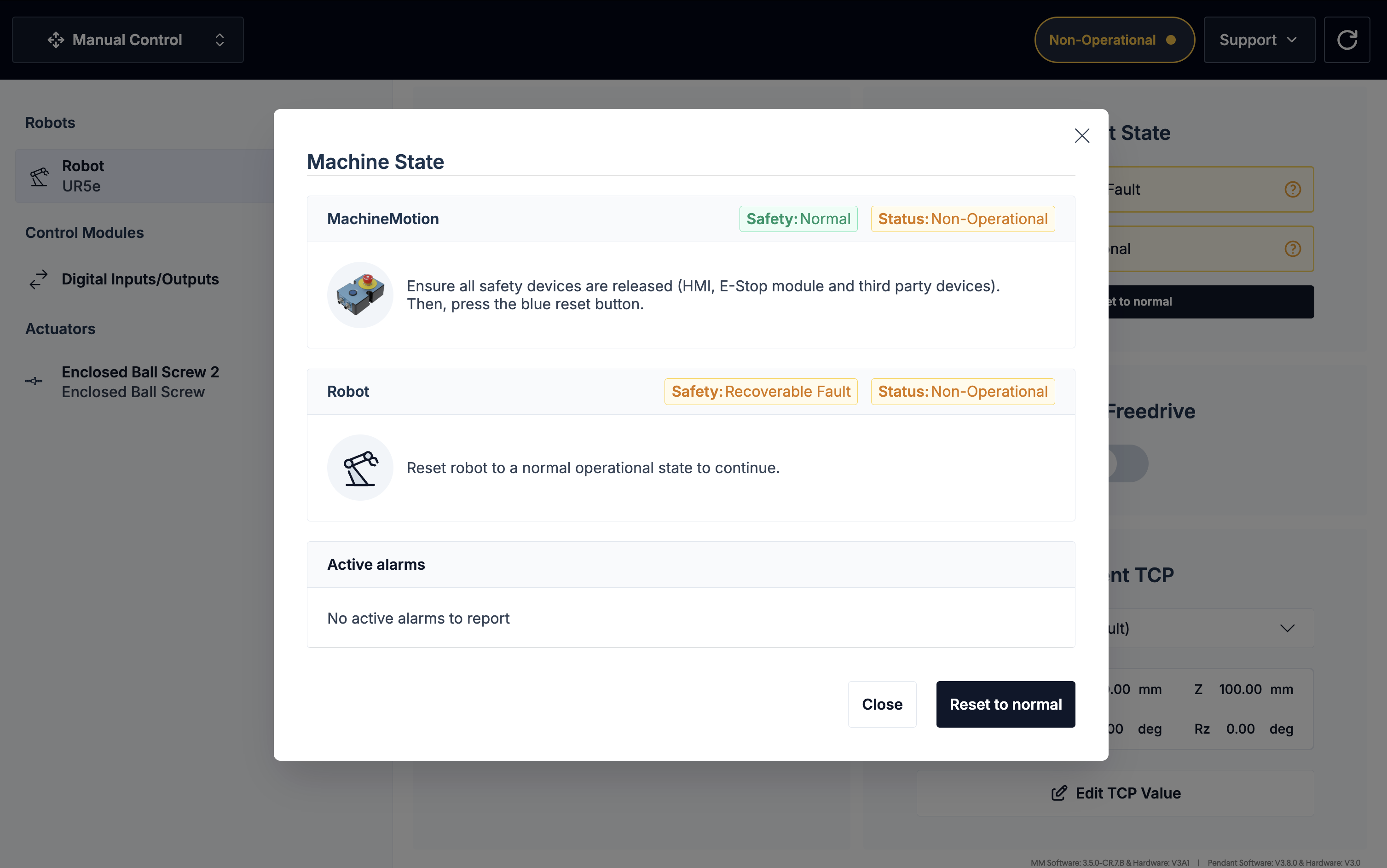
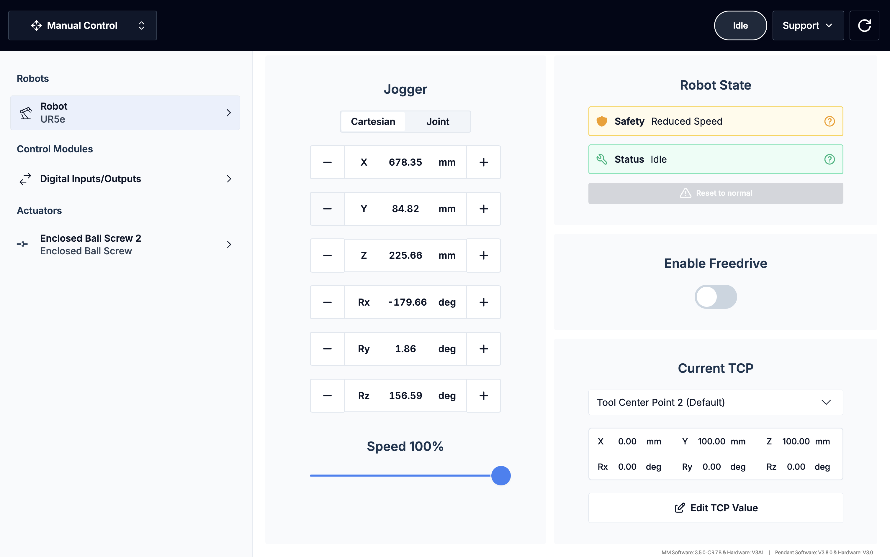
The table below outlines the various states the robot may find itself in, how it may have gotten into that state, and how to get out of it and return to normal operation.
State | Description |
|---|---|
Ready | Everything is functional and the application is running without errors.
|
Not ready | Occurs after a reset or fault-clearing event, usually brought on by an emergency stop or fault state. To return to a ready state, click “Reset to normal”.
|
Emergency stop | Occurs when a physical emergency stop button is pressed. Your MachineLogic program is stopped. To return to normal operation, release all emergency stop buttons and press a RESET button. If the reset procedure succeeds, your robot is now in a not ready state.
|
Recoverable fault | Occurs when the robot collides with an external object or person. Your MachineLogic program is stopped. In this state, the robot is back-drivable. Move the robot away from any possible collision and click “Reset to normal”. The robot should now be in a ready state.
|
Reduced mode | Occurs when a safety device wired into the reduced pin on the robot controller is triggered (ex: walking into an area guarded by an area scanner). Your MachineLogic program continues, but at a slower speed. It returns to full speed once the triggering fault is cleared. This mode does not trigger an alarm, but can be observed in the manual control view of the robot.
|
Fault | Occurs when a variation of errors not captured by the emergency or protective stop arise. Your MachineLogic program is stopped. To return to normal operation, the fault must be cleared on the robot’s native pendant before continuing. Once the fault is cleared, the robot is in a not ready state.
|
.png)
.png)
.png)
Note: MachineMotion does not support Safeguard Stop. Consequently, any Safeguard Stop event triggers an Emergency Stop, and that flow must be used to return to normal.
4.1.1 - Enabling the robot from the robot pendant
In certain cases (e.g. heavy safety breach), the robot may required to be re-enabled from the robot controller’s pendant. To get your robot back into an enabled state, simply select the State Indicator in the bottom left (see Figure 21a below). The robot may be completely powered down, start by powering it on (Figure 21a) and then enable it (Figure 21b). If the robot is already in an Idle state, enable it (Figure 21b).
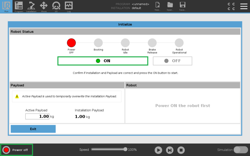
Figure 21a: Power on robot
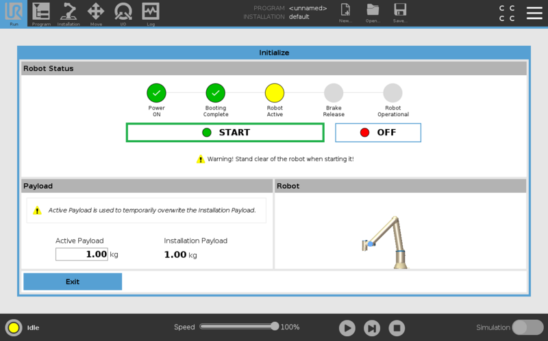
Figure 21b: Enable robot
4.2 - Motion planner errors
The “Move robot” command may encounter errors during the execution of your application. Such motion planner errors will appear in a toaster at the top of the Control Center, or in a banner at the bottom of MachineLogic:
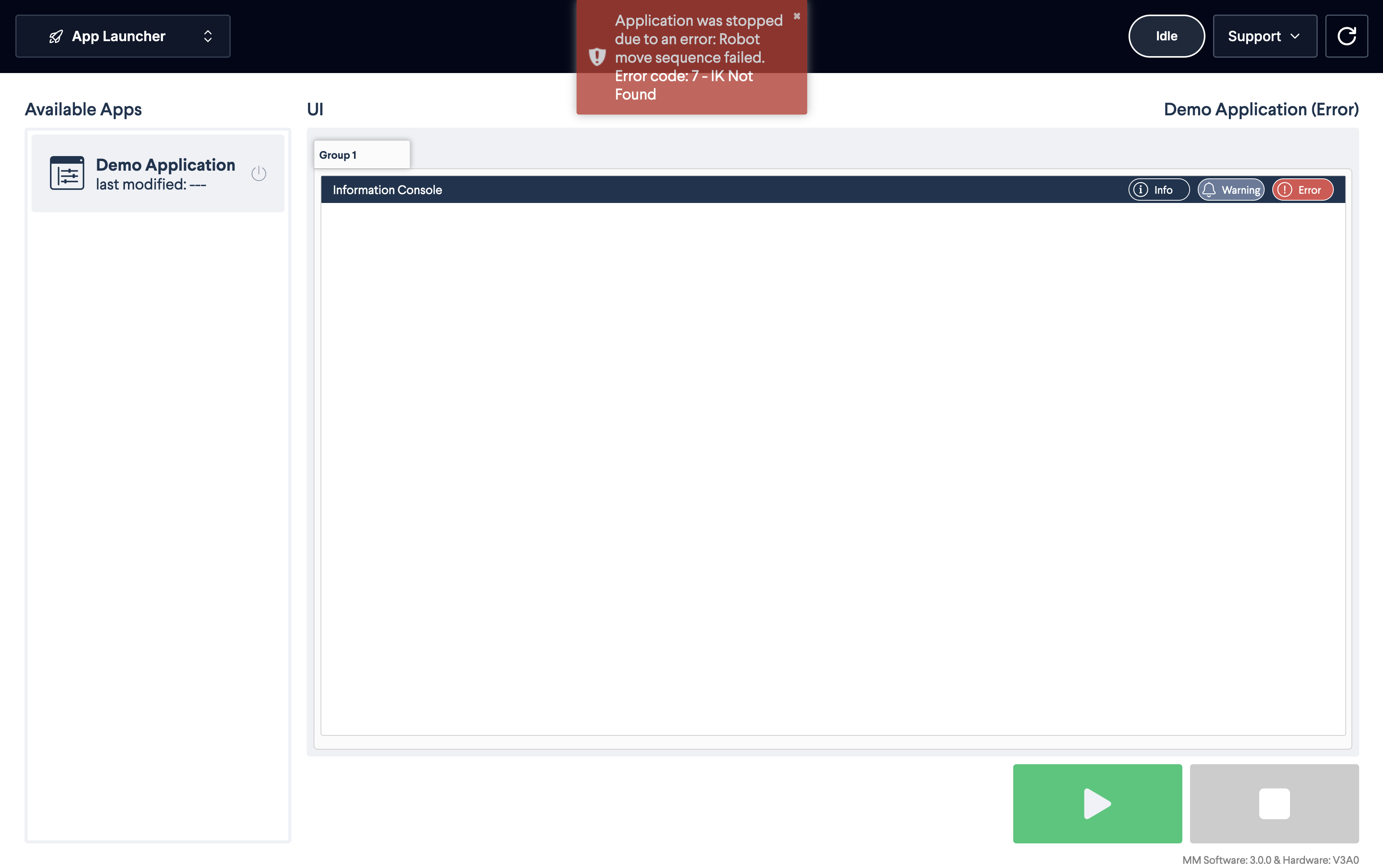
Figure 22a: Motion planner error
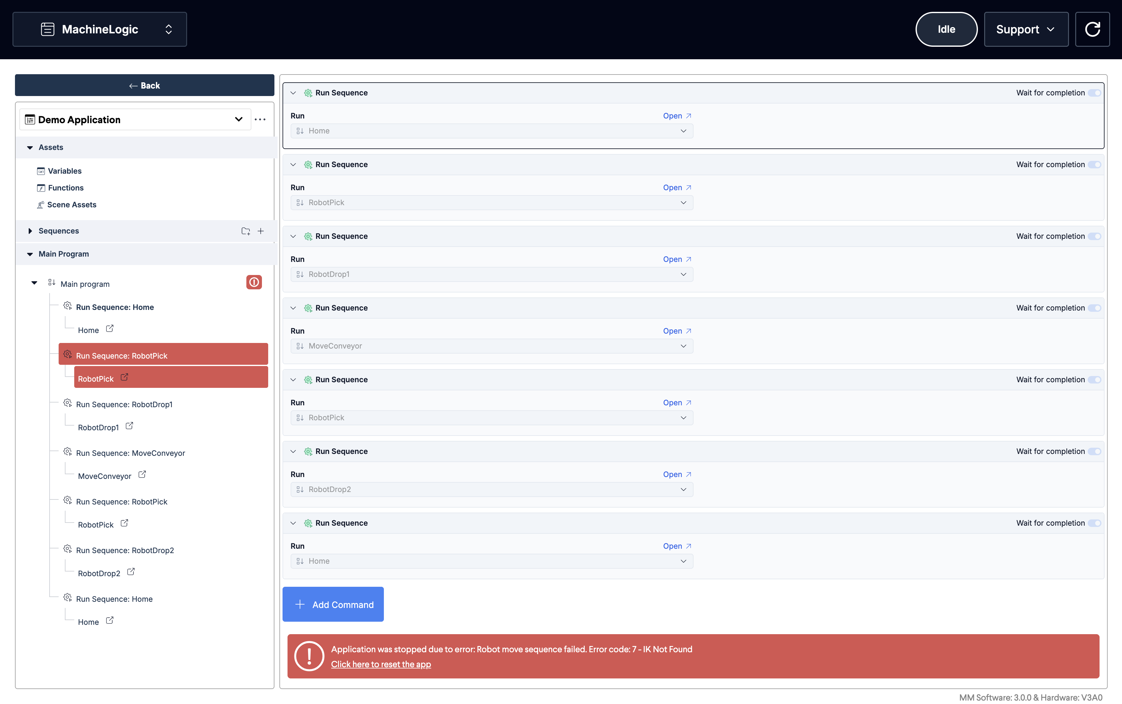
Figure 22a: Motion planner error in MachineLogic
The following table lists the errors you might encounter:
Error | Error Code | Description and Tips |
|---|---|---|
|
| |
|
| The motion plan would take a robot joint outside its operational range |
|
| The motion plan would lock the robot in a singularity |
|
| The motion plan would result in the robot colliding with itself |
|
| Motion planning could not compute valid inverse kinematics |
|
| The robot was not available for the motion planner |
|
| Requested blend radius is too small |
|
| Robot is already executing a motion |
|
| Goal type and constraint type do not match, one is joint and the other cartesian |
|
| General planner error |
5 - Programming with a Range Extender (7th Axis)
When using a range extender in conjunction with cartesian targets, a few extra steps are required to make sure the robot can reach each positions:
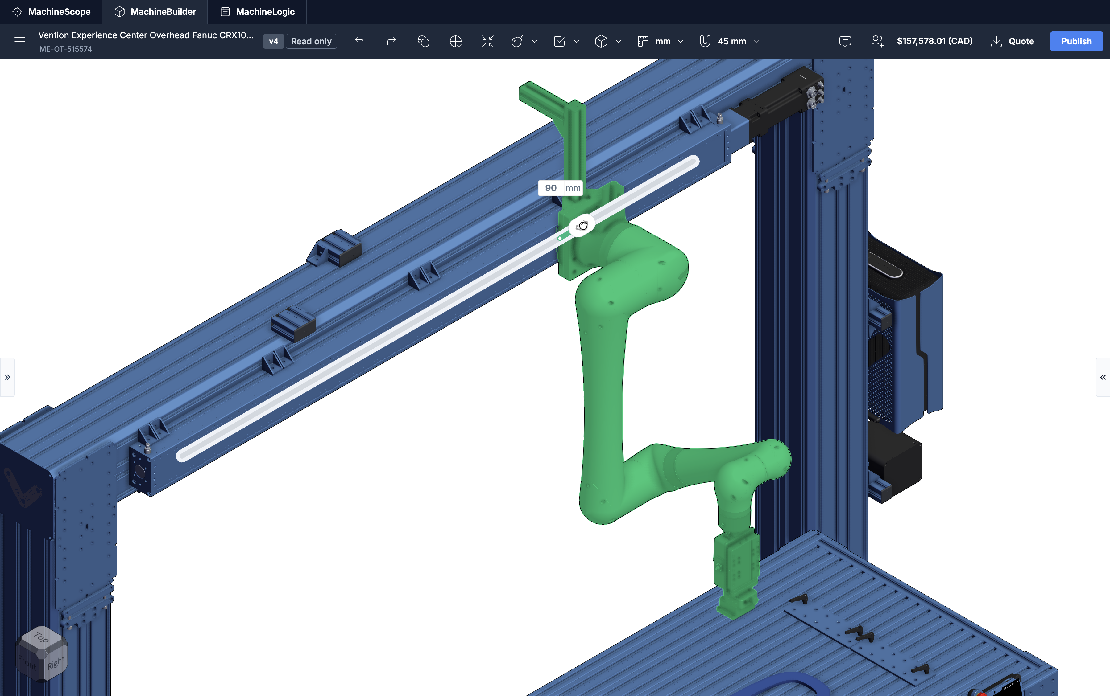
In the MachineBuilder scene, right-click the robot mounting plate attached to the range extender, and click “Edit degree of freedom”. Only the mounting plate and the robot should be highlighted in green. If the entire actuator and support structure is highlighted, then deselect it and repeat the procedure, paying close attention to right-clicking on the mounting plate itself.
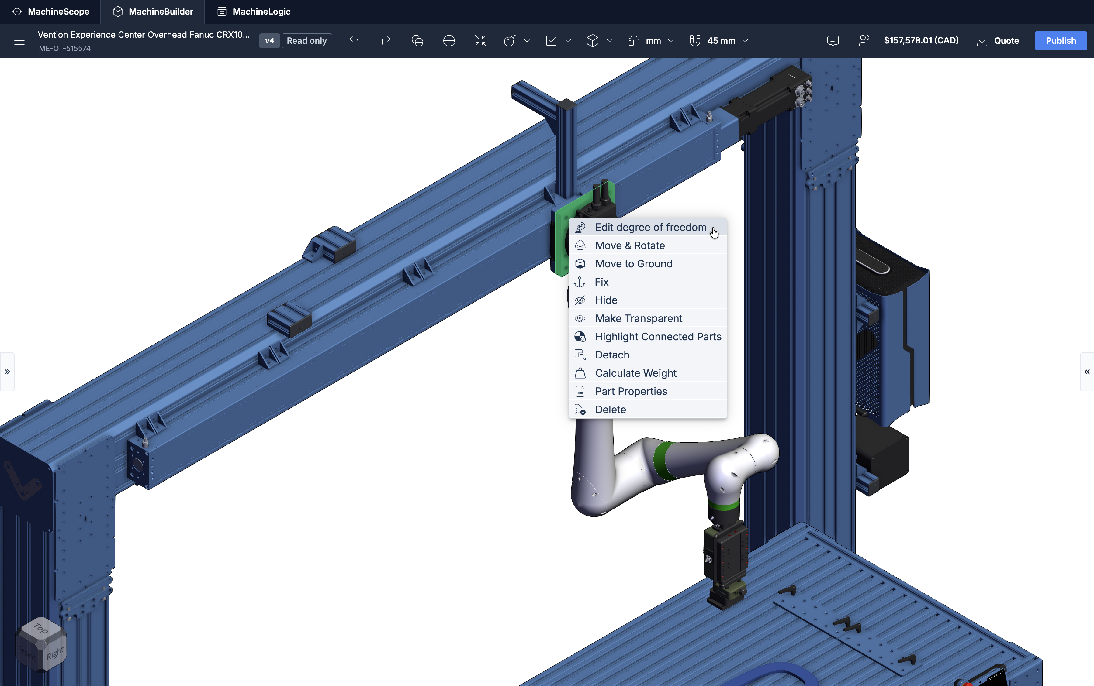
Move the robot to the desired positions by dragging the handle along the actuator.
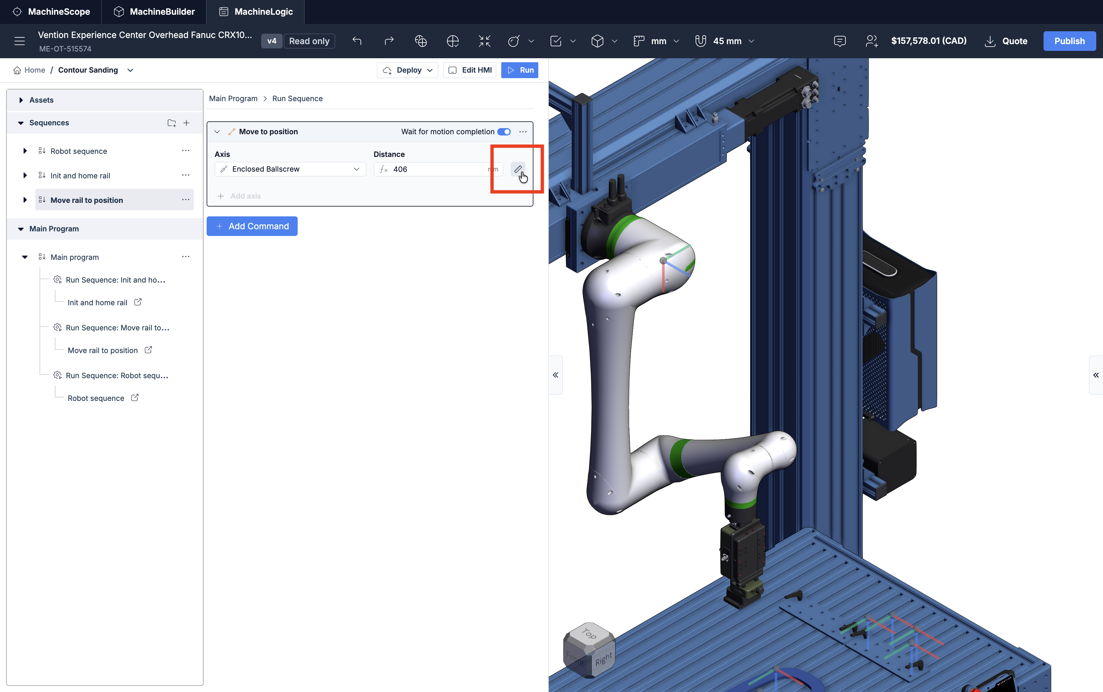
In your MachineLogic program, add a “Move to position” command and use the ruler button to record the current position of the range extender.
From the scene assets pane, insert new frames and targets while the robot is at the desired actuator position
Since all frames and targets are relative to the robot base, they will all move as the robot is moved by the range extender. Make sure that your application positions the range extender correctly using “Linear actuator” commands before using the scene assets relevant to that spatial configuration.